Showing posts with label NDT SERVICES. Show all posts

PENATRANT TESTING FOR FORGING

Dye penetrant inspection (DPI), also called liquid penetrant inspection (LPI) or penetrant testing (PT), is a widely applied and low-cost inspection method used to locate surface-breaking defects in all non-porous materials (metals, plastics, or ceramics). The penetrant may be applied to all non-ferrous materials and ferrous materials, although for ferrous components magnetic-particle inspection is often used instead for its subsurface detection capability. LPI is used to detect casting, forging and welding surface defects such as hairline cracks, surface porosity, leaks in new products, and fatigue cracks on in-service components.
Below are the main steps of Liquid Penetrant Inspection:
1. Pre-cleaning:
The test surface is cleaned to remove any dirt, paint, oil, grease or any loose scale that could either keep penetrant out of a defect, or cause irrelevant or false indications. Cleaning methods may include solvents, alkaline cleaning steps, vapor degreasing, or media blasting. The end goal of this step is a clean surface where any defects present are open to the surface, dry, and free of contamination. Note that if media blasting is used, it may "work over" small discontinuities in the part, and an etching bath is recommended as a post-blasting treatment.
Application of the penetrant to a part in a ventilated test area.
2. Application of Penetrant:
The penetrant is then applied to the surface of the item being tested. The penetrant is allowed "dwell time" to soak into any flaws (generally 5 to 30 minutes). The dwell time mainly depends upon the penetrant being used, material being tested and the size of flaws sought. As expected, smaller flaws require a longer penetration time. Due to their incompatible nature one must be careful not to apply solvent-based penetrant to a surface which is to be inspected with a water-washable penetrant.
3. Excess Penetrant Removal:
The excess penetrant is then removed from the surface. The removal method is controlled by the type of penetrant used. Water-washable, solvent-removable, lipophilic post-emulsifiable, or hydrophilic post-emulsifiable are the common choices. Emulsifiers represent the highest sensitivity level, and chemically interact with the oily penetrant to make it removable with a water spray. When using solvent remover and lint-free cloth it is important to not spray the solvent on the test surface directly, because this can remove the penetrant from the flaws. If excess penetrant is not properly removed, once the developer is applied, it may leave a background in the developed area that can mask indications or defects. In addition, this may also produce false indications severely hindering your ability to do a proper inspection.
4. Application of Developer:
After excess penetrant has been removed a white developer is applied to the sample. Several developer types are available, including: non-aqueous wet developer, dry powder, water suspendable, and water soluble. Choice of developer is governed by penetrant compatibility (one can't use water-soluble or suspendable developer with water-washable penetrant), and by inspection conditions. When using non-aqueous wet developer (NAWD) or dry powder, the sample must be dried prior to application, while soluble and suspendable developers are applied with the part still wet from the previous step. NAWD is commercially available in aerosol spray cans, and may employ acetone, isopropyl alcohol, or a propellant that is a combination of the two. Developer should form a semi-transparent, even coating on the surface.
The developer draws penetrant from defects out onto the surface to form a visible indication, commonly known as bleed-out. Any areas that bleed-out can indicate the location, orientation and possible types of defects on the surface. Interpreting the results and characterizing defects from the indications found may require some training and/or experience [the indication size is not the actual size of the defect]
5. Inspection:
The inspector will use visible light with adequate intensity (100 foot-candles or 1100 lux is typical) for visible dye penetrant. Ultraviolet (UV-A) radiation of adequate intensity (1,000 micro-watts per centimeter squared is common), along with low ambient light levels (less than 2 foot-candles) for fluorescent penetrant examinations. Inspection of the test surface should take place after 10 to 30 minute development time, depends of product kind. This time delay allows the blotting action to occur. The inspector may observe the sample for indication formation when using visible dye. It is also good practice to observe indications as they form because the characteristics of the bleed out are a significant part of interpretation characterization of flaws.
6. Post Cleaning:
The test surface is often cleaned after inspection and recording of defects, especially if post-inspection coating processes are scheduled.

MAGNETIC PARTICLE FOR FORGING

Magnetic particle inspection (often abbreviated MT or MPI) is a nondestructive inspection method that provides detection of linear flaws located at or near the surface of ferromagnetic materials. It is viewed primarily as a surface examination method.

Basic principle
The part to be inspected is magnetized which produces lines of force or flux lines within the item. Flaws and imperfections in the item distort these flux lines causing them to ‘leak’ out.
These areas of flux leakage create regions of magnetic polarity on the surface of the item, and the magnetic particles applied to the surface collect at these areas forming a visible indication seen by the inspector.

Two separate magnetizations in different directions are necessary to locate flaws in all orientations.

The magnetic particles are very small ferromagnetic oxides that are chemically dyed to provide contrast against the background of the part being inspected.


MT has several advantages. The method is quick and simple to perform. The results are instantaneous and the indications appear directly on the surface of the part. This method of inspection may work through coatings such as cadmium and chrome plating and black oxide.
The single largest limitation to this method is that it is applicable only to ferromagnetic materials (steel). Nonferrous materials (aluminum, titanium, magnesium, copper, etc.) cannot be inspected using this method.
Demagnetization is a necessary step to remove residual magnetism that may interfere with subsequent processes (e.g., plating, welding). This is typically accomplished using an AC coil

ULTRASONIC TESTING FOR FORGING

In ultrasonic testing, very short ultrasonic pulse-waves with center frequencies ranging from 0.1-15 MHz and occasionally up to 50 MHz are launched into materials to detect hidden cracks, voids, porosity, and other internal flaws or to characterize materials. The technique is also commonly used to determine the thickness of the test object.
High frequency sound waves reflect from flaws in predictable ways, producing distinctive echo patterns that can be displayed and recorded by portable instruments. Ultrasonic testing is completely nondestructive and safe, and it is a well-established test method in many basic manufacturing, process, and service industries, especially in applications involving welds and structural metals. 
 It works on pulse-echo method. The sound pulse coming from the transmitter is radiated in a beam through a given medium at a specific speed or velocity, in a predictable direction, and when they encounter a boundary with a different medium they will be reflected. 
 All sound waves oscillate at a specific frequency, or number of vibrations or cycles per second, which we experience as pitch in the familiar range of audible sound. Human ears can respond to sound vibrations, which have frequencies in the range of 20Hz to 20kHz. While the majority of ultrasonic flaw detection applications utilize frequencies between 500 KHz to 10 MHz. At frequencies in the megahertz range, sound energy does not travel efficiently through air or other gasses, but it travels freely through most liquids and common engineering materials. 
The speed of a sound wave varies depending on the medium through which it is traveling, affected by the medium's density and elastic properties. In steel the velocity of sound wave is 6*1000000 mm/sec.
 Any type of wave will have an associated wavelength, which is the distance between any two corresponding points in the wave cycle as it travels through a medium. Wavelength is related to frequency and velocity by the following
λ = v/f 
where
λ = wavelength
v = sound velocity
f = frequency 
Wavelength is a limiting factor that controls the amount of information that can be derived from the behavior of a wave. In ultrasonic flaw detection, the generally accepted lower limit of detection for a small flaw is one-half wavelength. Anything smaller than that will be invisible. In ultrasonic thickness gauging, the theoretical minimum measurable thickness one wavelength. 


PENETRANT TESTING FOR WELDING

Dye penetrant inspection (DPI), also called liquid penetrant inspection (LPI) or penetrant testing (PT), is a widely applied and low-cost inspection method used to locate surface-breaking defects in all non-porous materials (metals, plastics, or ceramics). The penetrant may be applied to all non-ferrous materials and ferrous materials, although for ferrous components magnetic-particle inspection is often used instead for its subsurface detection capability. LPI is used to detect casting, forging and welding surface defects such as hairline cracks, surface porosity, leaks in new products, and fatigue cracks on in-service components.
DPI is based upon capillary action, where low surface tension fluid penetrates into clean and dry surface-breaking discontinuities. Penetrant may be applied to the test component by dipping, spraying, or brushing. After adequate penetration time has been allowed, the excess penetrant is removed and a developer is applied. The developer helps to draw penetrant out of the flaw so that an invisible indication becomes visible to the inspector. Inspection is performed under ultraviolet or white light, depending on the type of dye used - fluorescent or nonfluorescent (visible).

Inspection steps:
1. Pre-cleaning:
The test surface is cleaned to remove any dirt, paint, oil, grease or any loose scale that could either keep penetrant out of a defect, or cause irrelevant or false indications. Cleaning methods may include solvents, alkaline cleaning steps, vapor degreasing, or media blasting. The end goal of this step is a clean surface where any defects present are open to the surface, dry, and free of contamination. Note that if media blasting is used, it may "work over" small discontinuities in the part, and an etching bath is recommended as a post-blasting treatment. Application of the penetrant to a part in a ventilated test area.

2. Application of Penetrant:
The penetrant is then applied to the surface of the item being tested. The penetrant is allowed "dwell time" to soak into any flaws (generally 5 to 30 minutes). The dwell time mainly depends upon the penetrant being used, material being tested and the size of flaws sought. As expected, smaller flaws require a longer penetration time. Due to their incompatible nature one must be careful not to apply solvent-based penetrant to a surface which is to be inspected with a water-washable penetrant.

3. Excess Penetrant Removal:
The excess penetrant is then removed from the surface. The removal method is controlled by the type of penetrant used. Water-washable, solvent-removable, lipophilic post-emulsifiable, or hydrophilic post-emulsifiable are the common choices. Emulsifiers represent the highest sensitivity level, and chemically interact with the oily penetrant to make it removable with a water spray. When using solvent remover and lint-free cloth it is important to not spray the solvent on the test surface directly, because this can remove the penetrant from the flaws. If excess penetrant is not properly removed, once the developer is applied, it may leave a background in the developed area that can mask indications or defects. In addition, this may also produce false indications severely hindering your ability to do a proper inspection.

4. Application of Developer:
After excess penetrant has been removed a white developer is applied to the sample. Several developer types are available, including: non-aqueous wet developer, dry powder, water suspendable, and water soluble. Choice of developer is governed by penetrant compatibility (one can't use water-soluble or suspendable developer with water-washable penetrant), and by inspection conditions. When using non-aqueous wet developer (NAWD) or dry powder, the sample must be dried prior to application, while soluble and suspendable developers are applied with the part still wet from the previous step. NAWD is commercially available in aerosol spray cans, and may employ acetone, isopropyl alcohol, or a propellant that is a combination of the two. Developer should form a semi-transparent, even coating on the surface.
The developer draws penetrant from defects out onto the surface to form a visible indication, commonly known as bleed-out. Any areas that bleed-out can indicate the location, orientation and possible types of defects on the surface. Interpreting the results and characterizing defects from the indications found may require some training and/or experience [the indication size is not the actual size of the defect]

5. Inspection:
The inspector will use visible light with adequate intensity (100 foot-candles or 1100 lux is typical) for visible dye penetrant. Ultraviolet (UV-A) radiation of adequate intensity (1,000 micro-watts per centimeter squared is common), along with low ambient light levels (less than 2 foot-candles) for fluorescent penetrant examinations. Inspection of the test surface should take place after 10 to 30 minute development time, depends of product kind. This time delay allows the blotting action to occur. The inspector may observe the sample for indication formation when using visible dye. It is also good practice to observe indications as they form because the characteristics of the bleed out are a significant part of interpretation characterization of flaws.

6. Post Cleaning:
The test surface is often cleaned after inspection and recording of defects, especially if post-inspection coating processes are scheduled.

MAGNETIC PARTICAL TESTING FOR WELDING

Magnetic Partical Inspection (MPI) is used to detect casting, forging and weld surface defects such as hairline and fatigue cracks on in-service components.Magnetic particle inspection is a cost effective and efficient method of testing ferromagnetic components for discontinuities.In a fabrication environment it is used to locate surface and near surface weld defects.Magnetic Partical Inspection can also be used using fluorescent consumables and ultra-violet black lamps. This is a common technique for the inspection of turbine blades.
Magnetic particle Inspection (MPI) is a non-destructive testing (NDT) process for detecting surface and slightly subsurface discontinuities in ferromagnetic materials such as iron, nickel, cobalt, and some of their alloys and must be performed to worldwide standards such as EN473 and ISO9712 by qualified personnel. The process puts a magnetic field into the part. The piece can be magnetized by direct or indirect magnetization. Direct magnetization occurs when the electric current is passed through the test object and a magnetic field is formed in the material. Indirect magnetization occurs when no electric current is passed through the test object, but a magnetic field is applied from an outside source. The magnetic lines of force are perpendicular to the direction of the electric current which may be either alternating current (AC) or some form of direct current (DC) (rectified AC).
The presence of a surface or subsurface discontinuity in the material allows the magnetic flux to leak, since air cannot support as much magnetic field per unit volume as metals. Ferrous iron particles are then applied to the part. The particles may be dry or in a wet suspension. If an area of flux leakage is present, the particles will be attracted to this area. The particles will build up at the area of leakage and form what is known as an indication. The indication can then be evaluated to determine what it is, what may have caused it, and what action should be taken, if any.


ULTRASONIC TESTING FOR WELDING

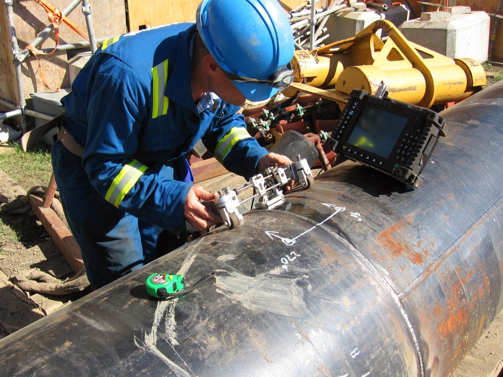
Ultrasonic inspection uses high frequency sound waves to detect imperfections or changes in properties within the materials. It can also be used to measure the thickness of a wide range of metallic and non-metallic materials where access from one side is available.


STEEL CASTING


Steel casting is a specialized form of casting involving various types of steel. Steel castings are used when cast irons cannot deliver enough strength or shock resistance

In the specification process for steel castings, there are three key words which should be understood.
These are
  • Specifications
  • Standards
  • Codes.
Specifications
   A specification is a form of standard, which precisely states a set of requirements to be satisfied by the casting. Some of these requirements might be chemical composition, mechanical properties, repair procedures, or any other requirement that is necessary to develop the quality of the casting needed for its end use. Specifications for steel castings are sometimes expanded or limited by standards and codes.
Standard
   A standard can be defined as a specification, test method, definition, or recommended practice that has been approved by a nationally recognized specification-writing body such as ASTM (American Society for Testing and Materials), ISO (international Organization of Standards), or SAE (Society of Automotive Engineers). A standard can be further be defined as a document which details properties, processes, dimensions, materials composition, relationships, or concepts. This connotation follows Webster's definition of "something set up and established by authority as a rule for the measure of quantity, weight, extent, value, or quality." It can be seen then that there is some overlapping between specifications and standards, and for that reason the two terms are often used interchangeably where steel castings are concerned.

Code
   The word " code " is a term of much broader meaning than either specification or standard and can best be described as a set of rules established by a recognized authority such as the American Society of Mechanical Engineers' (ASME), Boiler and Pressure Vessel Code or the United States of America Standards Institute's (USASI) code for pressure Piping. In adopting the rules that make up the various codes, consideration is generally based on health, safety, and environmental protection. The code-formulating bodies .


FORGING

Forging is a manufacturing process involving the shaping of metal using localized compressive forces. Forging is often classified according to the temperature at which it is performed: "cold", "warm", or "hot" forging. Forged parts can range in weight from less than a kilogram to 580 metric tons. Forged parts usually require further processing to achieve a finished part. Forging as an art form started with the desire to produce decorative objects from precious metals. Today, forging is a major world-wide industry that has significantly contributed to the development of man.

There are many different kinds of forging processes available, however they can be grouped into three main classes
  • Drawn out: length increases, cross-section decreases
  • Upset: length decreases, cross-section increases
  • Squeezed in closed compression dies: produces multidirectional flow
Common forging processes include:
  • Roll forging
  • Swaging
  • Cogging
  • Open-die forging
  • Impression-die forging
  • Press forging
  • Automatic hot forging and upsetting.

WELDING

Welding is a fabrication or sculptural process that joins materials, usually metals or thermoplastics, by causing coalescence. This is often done by melting the workpieces and adding a filler material to form a pool of molten material (the weld pool) that cools to become a strong joint, with pressure sometimes used in conjunction with heat, or by itself, to produce the weld. This is in contrast with soldering and brazing, which involve melting a lower-melting-point material between the workpieces to form a bond between them, without melting the workpieces.

Many different energy sources can be used for welding, including a gas flame, an electric arc, a laser, an electron beam, friction, and ultrasound. While often an industrial process, welding may be performed in many different environments, including open air, under water and in outer space.